Hardware Setup and Wiring
This document describes how to power the ENTS sensing node, connect digital and analog sensors, and wire measurement circuits.
1. Powering the Board
The ENTS sensor board can be powered through either USB-C or a dedicated external battery connector.
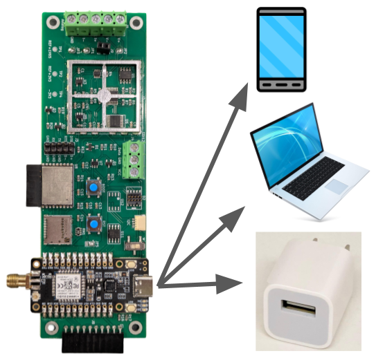
Power Options
- USB-C Port: Connect the board's USB-C port to a standard USB power adapter (5V DC, >= 500mA) or to a computer USB port.
- Battery Header (J9): Connect a 3.7V Li-ion or LiPo battery pack. The header includes integrated charge controller logic and reverse-polarity protection.
When powering on the board, ensure the power slide switch is in the ON position (slid toward the nearest board edge).
2. Sensor Connections
The ENTS board provides screw terminals and digital headers along the bottom and right edges of the PCB.
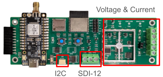
Digital Interfaces (Bottom Edge)
- SDI-12 Interface (3-Pin Screw Terminal):
- Used for digital environmental probes such as the METER TEROS 11/12 soil moisture, temperature, and electrical conductivity sensors.
- Pinout:
12V/VCC,DATA,GND. - I2C Interface (JST Header):
- Used for digital environmental sensors (such as Sensirion SHT temperature/humidity or Bosch pressure sensors).
- Pinout:
3V3,SCL,SDA,GND.
3. Analog Voltage and Current Measurements (Right Edge)
The 5-position screw terminal on the right side of the board connects to the precision differential analog measurement frontend.
Simultaneous Voltage and Current Wiring
To simultaneously measure voltage and current across an energy-harvesting cell (such as a soil microbial fuel cell) using a shunt resistor \(R = 2\text{ k}\Omega\):
(+) Positive Lead ---+-------------------------> [V+] Terminal
                     |                          [V-] Terminal
                     +----[ 2 kΩ Resistor ]----> [I+] Terminal
                                                [I-] Terminal
(-) Negative Lead -----------------------------> [GND] Terminal
Terminal Definitions
| Terminal | Signal | Description |
|---|---|---|
V+ |
Differential Voltage Positive | Positive voltage terminal of the load or energy source. |
V- |
Differential Voltage Negative | Negative terminal for differential voltage sampling. |
I+ |
Shunt Resistor High Side | High-side connection to the current-sensing resistor. |
I- |
Shunt Resistor Low Side | Low-side connection to the current-sensing resistor. |
GND |
System Ground | Common ground reference for single-ended measurements. |
4. Measurement Jumper Configurations
The board includes surface-mount solder jumpers (JP1, JP2, JP3) to switch between measurement modes:
Independent Inputs (Default Mode)
JP1,JP2,JP3: Unbridged (Open)Rsense1: Not populated (DNP)- Application: Differential voltage and current channels are fully isolated from ground. Use this mode when measuring signals with independent ground potentials.
Common Ground Mode
JP1orJP3: Bridged to ground- Application: Ties the negative measurement terminals directly to system ground for single-ended low-side sensing.